related links to vishia articles:
-
GenSfn_SmlkApproaches.html: common text about S-FunctionBlocks in Simulink
-
GenSfnFromHeader.html: Generation of S-FunctionBlocks from information in headerfile.
-
../Smlk_Libs/Smlk_Libs_Sw.html: Libraries vishia… for Simulink
-
../SmlkInspc/DataStruct_Inspc.html: Function Block group DataStruct_Inspc for Data Connection of modules
-
vishia.org/emC: embedded multiplatform C/++ concept.
-
vishia.org/emC/html/Ctrl/Overview.html: and the referenced articles.
-
vishia.org/Inspc tool
related links in internet:
-
https://www.embedded-software-engineering.de/grafische-objektorientierte-c-programmierung-mit-simulink-a-726729/: This was from my presentation of the ObjectOriented Approach of FBlocks on the ESE Kongress 2017.
1. Approach
The approach of (all) Function Block modelling tools (Simulink, Modelica etc.) are dataflow oriented. This is traditional. The data flow determines the order of execution. Some FBlocks store data inside.
The Object Oriented Programming has never reached the FBlock world, in the official tools. Why not? Tradition.
What is Object Oriented Programming? It is firstly the definition of associated data with associated operations. Secondly a system of abstraction and inheritance is self-evident, which is established in the known Object Oriented languages, inclusively late dynamic binding.
If a graphical module contains internal data (its state), the operations which are associated to the data flow in dedicated step times are the operations to the data; and it is ObjectOriented, in fact. But the access to this object is only limited to the data flow step operations. The transport of the data in the flow is like an event. The event itself is the fact, that the next module should be executed; and the data to this event are given with this data flow. The data flow is not only a data connection, it defines also the execution order.
This article describes an existing system of S-Functions which can be connected and used in an ObjectOriented manner.
2. Using C/++-S-FunctionBlocks for Object Orientation
If a C/++ S-FunctionBlock (FBlock) is used, it can also contain data. It is an Object as mentioned in the immediately above chapter Approach. Its step operations are the operations to the data inside the FBlock.
But additionally the FBlock can transfer a reference to its own internal data to other FBlocks. These FBlocks can (should) be coordinated with each other. So we get some coordinated FBlocks. One can access data from the other. So the data flow principle is subordinated. The data access is done (in C/++ level) also via this reference. This is the same as associated (or aggregated) Objects in the ObjectOrientation, able to present also in UML (Unified Modelling Language).
If one of the FBlocks contains the data, dedicated other related FBlocks are present as access operations (getter, setter), then we have enhanced the ObjectOrientation of a simple FBlock to disperse accesses in the whole graphical model. Some Blocks can be used as operations ("methods"), which can be called from any other parts of the software, here graphical.
Hence the important fact is the relation between determined FBlocks with references to more elaborately using ObjectOriented accesses.
This system supports also abstraction and inheritance:
-
It is possible to define another FBlock with data as extending FBlock, which refers a base FBlock. A FBlock does only create its internal data if it is not extended. Elsewhere it gets the data reference from its extending one. Hence only one data creation occurs, in the most extending FBlock. It is a quest of configuration of the C/++ software in the FBlocks.
-
It is possible to use late dynamic binding in some operations from the base FBlock. Hence the operation of the step time depends on the extension. This is simple able to do if C++ is used, using virtual operations, or another adequate solution (internal function pointer table).
The possibility of extension (and abstraction from other side view) is important for graphical modeling too:
-
If a module is ready and tested, it should not be changed in a reusing situation with some other details.
-
Extension in a extending graphical module introduces the specific necessary things.
3. How to present the reference to data between FBlocks
In classic ObjectOriented approaches, often presented with UML (Unified Modeling Language) the references between Objects, associations, aggregations and compositions are presented in Class or ObjectModelDiagrams. The kind of setting references is part of the implementation. Compositions (references to own sub Objects) are created of course on startup of the Object. Aggregations (non changeable references to other Objects) are connected either via constructor arguments: pointer to the aggregated Objects, or in a specific startup operation. Associations are references which can be changed in runtime, with specific operations.
Using the graphical programming with FBlocks, the system of setting references is more obvious. References are simple connections between FBlocks. A reference as association can be switched (using switching FBlocks). Often references are given on startup as aggregations. This reference connections are like data flow in an Step time which is organized for "initializing". The data flow is from the reference presenter to the consumer. Hence the direction of the arrow is in opposite to a Class Diagram. A Class Diagram shows the relation of usage: The referencing class/object points to the referenced one. A FBlock diagram has the arrow from the referenced FBlock (presents its address) to the referencing one (can use the address to access).

Image: Example model with OrthOsc as ObjectOriented FBlock
The image above shows a complex example in Simulink with ObjectOriented FBlocks:
The FBlock OrthOsc2_FB (middle) has a filter functionality, explored and developed with Simulink tooling, but then established as C/++ Function (Simulink S-Function). It uses parameter. The parameter are calculated in an own Param_OrthOsc2_FB, left side. The param_OrthOsc1 offers its data reference to the orthOsc1, which can use the parameter data by immediate access into the Param_OrthOsc2_FB FBlock. Hint: Of course this FBlocks are part of a library for modelling. The name of the FBlock in the Library is not shown immediately in Simulink, but via style guide it is the name of the last output written with first upper case (as class names in Java). The name of the FBlock presented below the FBlock symbol is the instance name.
The parameters depend on the frequency, the fq input. But the calculation of new parameters from a given frequency is done in a longer step time. Because: It needs more calculation time for sin and cos calculations, and it is not necessary to calculate it in the fast step time. The step times are presented here by different colors. The red color is the fast step time (for example 50 µs for electrical signals). - Hence the parametrization is another operation, another FBlock. The other reason for an own FBlock: Parameters can be used for more as one OrthOsc2_FB FBlock. Then the references is connected to all using ones.
The angle gi is prepared in a specific FBlock Angle_abgm_FB. This FBlock is separated from the OrthOsc2_FB though it works in the same step time. The reason: The angle can be used via this reference in some other FBlocks too. The preparation of the angle value from a wrapping integer presentation to a and b coordinates needs a sin and cos calculation, it needs some time and should only one time performed in the fast step time. The reference is offered from this FBlock angle1 to the orthOsc1 via its internal reference. This reference can be used by other proper FBlocks too if necessary. Then only the references should be adequate wired. If this operations are modeled in Simulink (in an own subsystem) the output will be a bus (with more signals). A simple bus is also handled as reference in code generation, there is no difference, the code generation is optimized. But, handling a bus in a diagram is some more difficult in comparison with the simple reference handle, it is an uint32 type. This reference is really included as aggregation in the OrthOsc2_FB class. Such a referenced bus is not intended in a maybe comprehensiv bus structure, which may present the data of OrthOsc2_FB. Deal with handle is more simple.
The both FBlocks calcmagn1 and calcdq right side are connected with the thiz reference in the fast (red) step time. They are get-operations (getter) without own data, as part of the OrthOsc2_FB class. Also set operations are possible. They can be dispersed in the model. Getter and setter are Operation-FBlock without own data, whereas the other are Object-FBlocks with its data.
4. Type of references, reference type check
On modeling level the references are from type uint32 because whether Simulink nor other simulation tools knows pointer types.
Simulink knows a bus. A bus is handled in code generation also as reference. It seems to be possible to use bus definitions in Simulink for the references. But this has disadvantages:
-
1) Buses are not simple to handle in Simulink. It is not a very good solution in detail.
-
2) Buses are possible to map to data structures in C language, also with defining buses from given a data
struct. This seems to be near to this approach. But it is an additional complicating thing. -
3) Referencing a bus from another bus is not possible. Also in code generation a bus as element of a superordinate bus is not implemented as reference, and results in data copying. This is the experience with Simulink till version ~2018b.
Hence another solution was searched and found.
Firstly a self-evident idea is, that the references are presented immediately by its memory addresses as a void* approach presented by unsigend int. But this has also disadvantages in a Simulink model:
-
Simulink does not know the necessary uint64 type (experience till version 2918b, no newer information). But 64 bit width addresses are necessary to run in Windows-64 system.
-
The uint64 type is oversized for a target system with 32 bit addresses.
So the following solution to present references was found:
-
In Simulink the references are handle values presented as
uint32in a small range starting from 1. You can see and compare this values to see the forwarding data flow of references. -
In the implementation of the S-FBlocks in Simulink there is a central array valid for all S-Functions (that are different dll, Dynamic Linked Libraries). The handle is the simple index in this array, the array contains the 64-bit address values.
-
For a 32-bit-target system the same connections with
uint32type are the immediately memory addresses, without overhead.
It means, all in all, it is dealt with addresses in the model with a void* typing approach.
Hence the type cannot be checked on compile time of the model. References on FBlocks can be worse connected. But - the phase of compilation and startup of simulation is nearly the same. It means a type check in the startup phase of run time is nearly the same as in compiling phase of the model.
If the model is checked (simulation was started), all connections are ok. Then the code generation can use the uint32 handle values immediately as references, with reinterpret_cast<…>(…) or the adequate C-language cast in the code generation or in manually programming to offer to the FBlock routines.
For the type check in startup run time a type designation via Reflection is used. It means all data struct for references should base on ObjectJc which contains a reference to the appropriate ClassJc. For the Simulation level this reflection information contains the real name of the type as String. But for running in a poor target the ObjectJc can be reduced to only one int32 value. The type need not be checked again in the target if it is checked proper in simulation. But for associations (switching references) or for safety a type check can be also done in the startup phase (init Routine) in the target, recommended on more rich targets (more processor power, memory etc). The implementation of an ObjectJc data struct as base of data has the necessary flexibility in the emC approach.
5. Initialization of aggregations
The references between Object-FBlocks are associations or aggregations, or inheritances. Especially for aggregations the wiring should be completely done in a startup phase before any functionality of step times is used. Simulink and also other tools do not offer a specific initialization process. Hence, for Simulink a specific Tinit step time is used. In the simulation engine this step time is cyclically invoked of course, but only the first few steps are necessary to initialize. The other cycles are empty in functionality. The ObjectOriented S-FBlocks has a state "initialized" or even not. This is coupled on the ObjectJc base data with the routines isInitialized_ObjectJc(…) and setInitialized_ObjectJc(…), see ObjectJc, chapter "The isInitialized_ObjectJc(…) state of an object".
For code generation this Tinit step time is generated in a specific routine for this step time, which need and should be executed only initially. In the Simulink Coder you should set some options to ensure that any step or sample time has its own routine. The init routine should be invoked initially in a while loop till the initialization is completed.
Why not only one step to initialize?
Initializing needs either data (values) or references as aggregations, or both: a reference whereby the referenced object should be initialized already with the correct values. Hence in a first step the initializing cannot be finished, if the source of an Object is not initialized in this step. Also the correct order of Objects for initializing does not help, because there are each-other or circular dependencies. They are not possible to avoid, aggregations in both direction may be necessary.
Any object contains the information isInitialized_ObjectJc(…), it is property of the ObjectJc base class (which is necessary also for type check, see above). If there are C/++-FBlocks which’s data are not based on ObjectJc, simple functionality which’s data are not presented outside, but it depends on correct initializing from other FBlocks, the state 'isInitialized' is stored in a S-Function-specific variable. For the target system it is sufficient that the init(…) step routine is called one time again after message 'all seems to be intialized' - because that FBlocks are guaranteed initialized in this last step if all sources are initialized.
In the image above "Example model with OrthOsc as ObjectOriented FBlock" the FBlock Param_OrthOsc2_FB can only be initialized if the fq on its input has a valid value. This frequency value may deliver from another source. It should be ready to use in the initial time, but maybe not in the first cycle of that. Only if Param_OrthOsc2_FB can calculate correct parameter proper to the frequency then the OrtOsc2_FB can work. This is the initializing chain in this example.
6. Implementation possibilities
The chapters above have described the idea and have named also the basics which will be found in the vishia.org/emC concept. It means that emC concept is necessary to use. You can use also some Controller FBlocks etc. immediately from there, and write your own functionality proper for that.
The remaining question is: How to generate the Simulink S-Function. This is answered in the article GenSfnFromHeader.html.
The other possibility is: Only modeling, and using existing S-FBlocks with cores from emC. This S-FBlocks are offered in ../Smlk_Libs/Smlk_Libs_Sw.html, the basic functionality in emC is shown in vishia.org/emC/html/Ctrl/Overview.html and the referenced articles.
For only modeling you can use data FBlocks for modeling data which are also ObjectOriented. That is described in ../SmlkInspc/DataStruct_Inspc.html. This S-Functions create data `struct`s only by parameterization in Simulink, of course with code generation due to the parameterization able to use with the Simulink Coder or also outside with manual written code using that generated one.
Last not least there is a vishia.org/Inspc tool and its S-FBlock implementation in Simulink which can be used to access to all data both in Simulink and also in the target system. This is of course independent of Simulink approaches (not a Simulink/Mathworks instrumentation).
7. Bus vs. Reference-Handle
@date=2020-01-12
This chapter compares the classic connection of Moduls via Bus and the connection via a reference It was a preliminary consideration before creating the reference-handle system.
Object Orientation
ObjectOrientation as such means, bundling of data to their operations. For Simulink FBs (Function Blocks) it means, any FBlock, or Module, has its specific data. The assembled data of a FBlock or Module can be presented and forwarded with the simulink standard equipment via a mux (Multiplexer) or via a bus. But how it is with set-operations. Show the right images of the following chapter:

The first image shows two modules. Originally it could have been one module, but a part of the too much functionality may be removed from stock. Now there is a data flow between the orginally associated functionality. A simple begin of confusion.
.
.
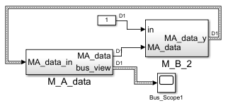 Some more data are necessary from
 M_B to M_A. The last one, the original or first, should be the 'module'- FBlock which holds the data in an Object Oriented approach. Some data are transferred from A to B.
But to rewrite to the data inside the operation M_B some back connections are needed, from the operation, which changes the data, back to the Module which holds the data. That is data flow, the original paradigm of Simulink.
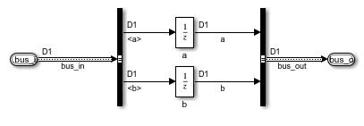
If the data should be consequently hold in the M_A it needs a storage. In a classic data-flow-oriented design the storage is inside any FBlocks, last not least usually it is a kind of the here shown unit delay.
Because of the data should be explicitely designed, unit delays are used explicitely in the 'module'-FBlock M_A. Because of its content should be get and set by several operations and the 'object oriented' data flow should be simple visible, left and right of them is a bus which’s definition defines the data of this ObjectOriented approach. Of course for vectorized data one unit delay is only necessary.
Yet the designer of the model could come to the idea to assemble the unit delay in the 'operation' module, because the new data are calculated there, it seems to be more simple. It is data-flow-oriented. But hence the architecture of the Object-Oriented software is disturbed, no more separation between data and the operation, no more assemble all data in one module.
The bus definition may be seen as elaborate and non-flexible. There is a more simple approach using special FBlocks as S-Function (in C) which holds the data internally instead using graphical unit delays. The FBlocks are textual parametrized in the Simulink model to define kind and number of data. No (C/++) programming is necessary. As additonal feature the internal values can be set from a file content [[TODO timesignal values], and the content is accesible via Socket connection if the Inspector-Service FBlock is connected with them.
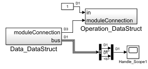
Hence the two modules are connected via a handle which is a reference to the data. Now it is really ObjectOriented. The handle is an identifier (numerical) for the module data on memory. It is the memory address for a 32-bit-System after code generation. For simulink usage the memory address may be 64 bit, and a problem of memory isolation exists between several mex moduls of the S-function. Hence the handle is used here, it is a 32 bit value, but in a lower range, it is an index to a memory address table.
One can ask, what about the dataflow principle: Well, there is a data flow, the module FBlock gives its information about the memory to its associated operation FBlock.
If the operation is only reading, the data flow adequate to the functional programming approach is considered. If the operation is writing, it is a writing operation for this module outside of the module FBlock in respect to Object Oriented Programming with private access of the own writing operation to the module. The only one extraordinariness for classic data flow /FBlock programming is: It is outside the module. The advantage: Improved design ability.
What about faulty connections, memory mismatch: That is proper. The receiving FBlock checks the content of the referenced memory via Reflection, the type should be match. Only suitable FBlocks can be connected together. A non conform connection is reported on start of the simulation as error.
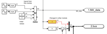
The module which holds the data contains a Function Block of type lib_Inspc/DataStructMng_Inspc from the lib_Inspc-Library. It has inputs for all data, maybe used as initial inputs only (the 3. and 4. input here) or in Runtime (the first 2 inputs here). The definition of input number and kind is given here with the simple textual parametrizing:
s1,s2;
=a, =b;
It defines the name of the 4 Inputs. The type depends from the wired signals (inherit) or can be defined in the parametrize area, also for array types. The = means, the input is the initial value only.
Here shown, the access to data is done with the small FBlocks designated as a and b. They are of type lib_Inspc/get_DataStruct_Inspc which the proper Parametrizing to access one value of the data.

The image right shows access and set of data. How to do rewrite of data without a back-connection (data-flow thinking). Of course, it is possible with a set-Operation. That is done with the two right FBs a and b. It are of type lib_Inspc/get_DataStruct_Inspc. The second input is the handle which refers the memory for the data. The first input is determined by the parametrizing for the selected data field in the data struct. The step time (sample time) can be any one. The data consistence is in the hands of the developer, some helper (locking mechanism, double buffering) is possible. In a classic dataflow design rate transitions cannot resolve any data consistence problem. But that is a more complex topic.